
After reading about Umberto’s amazing cycling experience across Italy in the last blog entry, we sadly had to admit that summer was really over. Then it is really time to sit again at your school desk and deal with a more technical topic. Therefore, this time I would like to introduce you to the basics of the Extended Finite Element Method or X-FEM. What does the extension in X-FEM stand for? Or, if you rather, what is the X factor of X-FEM?
Originally proposed by A. Hansbo and P. Hansbo [1], X-FEM is an advanced numerical technique that extends the range of applications of the more classical Finite Element Method (FEM), thanks to its geometric flexibility and the preservation of its accuracy even in complex topological configurations.
Before explaining the reasons for this gain in X-FEM, I first need to recall the main concepts in FEM theory. Used in most real-engineering problems, FEM is a numerical method used to solve Partial Differential Equations (PDEs) which model the dynamics of a physical system in a properly discretized domain. Indeed, the domain is typically divided into triangles (in 2D) or into tetrahedra (in 3D), called finite elements, which form all together the computational mesh. In the simplest case of linear FEM, the vertices of the finite elements are the points (or nodes) of the mesh where the solution is computed by solving a corresponding linear system. Then, such nodal solutions are combined with basis functions to represent the solution over the whole domain. Therefore, each mesh node corresponds to a degree of freedom (or dof) of the system and, in general, the more points are considered in the spatial discretization, the more accutate the results should be.
So how is the extension of X-FEM implemented in this framework? The key for the answer to this question resides in the enriched nature of the finite elements of X-FEM, which allows for solutions with internal discontinuities thanks to a proper treatment of the associated dofs.
But let‘s take another step back to better understand the context of my application of this numerical technique. In my Ph.D. research, I decided to adopt X-FEM to simulate the complex dynamics occurring in the so-called Wave Membrane Blood Pump, developed at CorWave SA (Clichy, France). Indeed, this novel pumping technology is based on the mutual interaction between the blood flow and an undulating polymer membrane, which results in an effective propulsion working against the adverse pressure gradient between the left ventricle and the aorta. Therefore, we are technically dealing with a 3D Fluid-Structure Interaction (FSI) problem with a thin immersed membrane that undergoes to large displacements. The X-FEM formulation for this challenging class of FSI problems was proposed in [2].
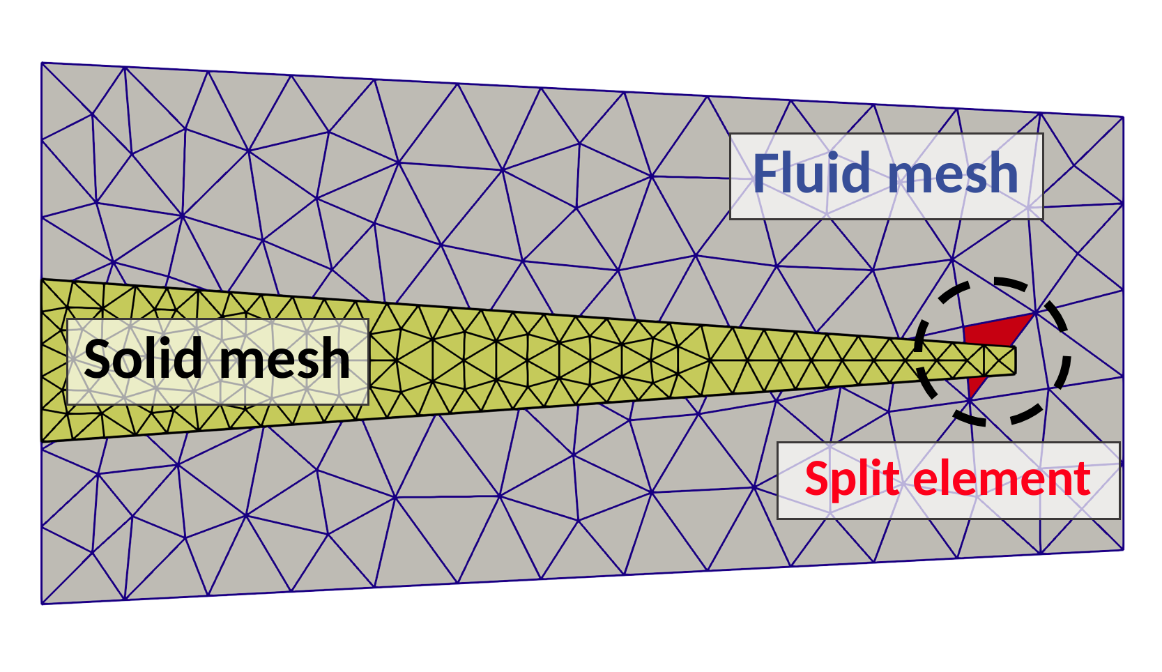
In FSI problems we need at least two meshes, one for the fluid and one for the structure. Since XFEM is an unfitted mesh technique, the two meshes lay on two different levels: in the background, there is the fluid mesh, that is fixed in time; while in the foreground, the structure mesh is free to move and intersect the underlying fluid mesh (see Figure 1). This means that some fluid mesh elements are cut by the structure mesh and perhaps split into multiple parts, where we need to represent the fluid solution. These fluid elements are called split elements. Notice that the split elements change in time because the structure mesh moves and intersects different fluid elements in different ways.
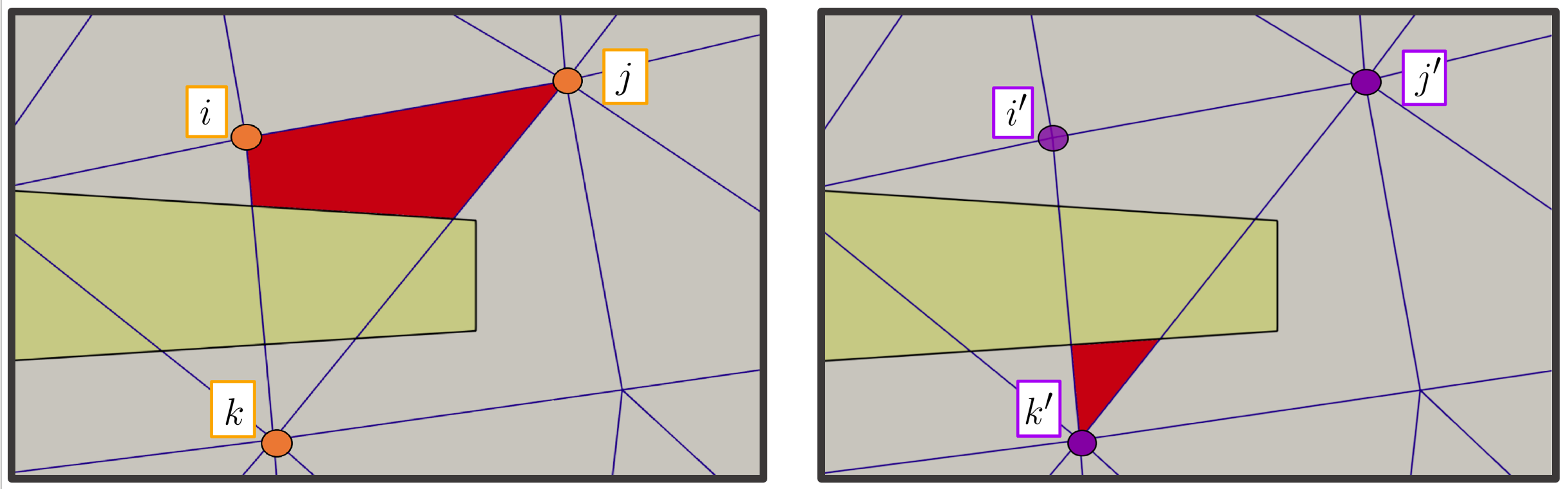
Now, here’s the trick of X-FEM. The split elements are enriched – or extended – by duplicating the corresponding dofs. Hence, we can use a set of dofs (i, j, k) to integrate the solution in one fluid visible portion of the split element, and the second set of dofs (i’, j’, k’) to integrate the solution in the other portion (see Figure 2). In this way, we end up with a simple way to embed a discontinuous solution in the same (extended) finite element using standard basis functions for the integration in space. Otherwise, in FEM framework, we would need to switch to discontinuous modal basis functions directly defined on the polyhedra generated by the intersetion, making the problem very stiff in three dimensions.
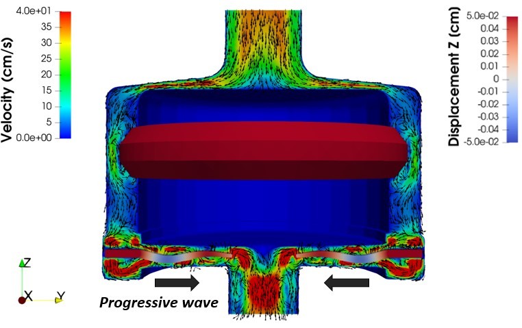
However, I must add that even the implementation of X-FEM is not simple, because we need to compute the intersections between the fluid and the structure meshes at each timestep and duplicate the dofs accordingly. Indeed, to my knowledge, this is the first time that X-FEM is applied on a real 3D industrial problem. Nevertheless, we validated the X-FEM-based numerical model against experimental data, proving that it is a reliable predictive tool for the hydraulic performance of the pump device [3]. In Figure 3, I report a snapshot from an X-FEM simulation of the FSI in the wave membrane blood pump, where we visualize the blood velocity field and the displcament field of the elastic wave membrane.
I hope I have “extended” a bit your knowledge. Sorry for the bad joke.
[1] A. Hansbo and P. Hansbo. An unfitted finite element method, based on Nitsche’s method, for elliptic interface problems. Computer methods in applied mechanics and engineering, 2002
[2] S. Zonca, C. Vergara, and L. Formaggia. An unfitted formulation for the interaction of an incompressible fluid with a thick structure via an XFEM/DG approach. SIAM Journal on Scientific Computing, 2018
[3] M. Martinolli, J. Biasetti, S. Zonca, L. Polverelli, C. Vergara, Extended Finite Element Method for Fluid- Structure Interaction in Wave Membrane Blood Pumps, submitted, MOX-Report 39/2020, 2020